

Optimizing the Intel RealSense LiDAR Camera L515 Range
This article will help you get the most out of your Intel® RealSense™ L515 LiDAR Camera. In this post we assume that the reader has basic knowledge of depth imaging and the many uses of depth in computer vision applications. If you are interested in a basic overview of depth, “The Beginner’s Guide to Depth” is a good place to start. The following sections will give a brief overview of the technology used in L515, provide useful information on how to adjust settings for your environment, and discuss limitations with the technology and how to avoid depth quality issues.
L515 LiDAR Technology Overview
The L515 Camera uses LiDAR technology to measure the distance from camera to object. Similar to other LiDAR systems, the L515 sends a laser beam and measures the returned time of the reflected light off an object. The L515 accomplishes this using a continuous coded IR beam. The time taken for the light to return to the camera is used to calculate the distance of the object. By repeating this process millions of times a second, the L515 is able to build a high resolution depth map of the scene. The figure below illustrates how scanning a scene using millions of points can build an image. In the case of L515, both an IR intensity image and a depth map are created.
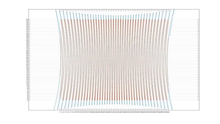
Figure 1. L515 creates a depth frame by scanning the scene with millions of points of information per second.
The difference with Intel RealSense LiDAR technology is that it uses an advanced miniaturized MEMS (micro-electromechanical system) mirror to scan the scene. The return light is collected by a single avalanche photodiode (APD) featuring low input referred noise (IRN), which in turn allows the L515 to be a power-efficient, high-accuracy LiDAR system at a very high resolution of up to 23 million depth points per second.
Camera Controls
Laser Power
As discussed earlier, the L515 uses a reflected light to calculate the distance of objects. If the reflected light is too strong, the receiver will saturate in the same way that a camera image can be overexposed. Oversaturating the receiver makes it impossible for the system to get any useful information resulting in poor or no depth. Conversely, if the reflected light is too weak, the system is unable to get useful information resulting in poor or no depth. You have control of the laser power and can adjust if necessary. It is recommended to start with the presets as these are designed to cover most situations. After you are familiar with the effect of the presets, adjusting the laser power manually may give better results considering the specific distance and objects for the use case. The laser power can always be set back to default if needed.
Receiver Gain
The light received by the camera can be amplified to help strengthen a weak signal. Increasing the receiver gain may be necessary if objects are far away or have poorly reflective surfaces. Decreasing the receiver gain may be necessary if the objects are close to the camera or are highly reflective. It is recommended to start with the presets as these are designed to cover most situations. After you are familiar with the effect of the presets, adjusting the gain manually may give better results considering the specific distance and objects for the use case. The gain can always be set back to default if needed.
Important Tradeoffs
Controlling laser power and receiver gain can help improve depth performance in some situations. However, there are tradeoffs that should be understood when adjusting these settings.
Table explaining the effects of increasing and decreasing L515 laser power and receiver gain
| Action | Pro | Con |
|---|---|---|
| Increase laser power | Easier to measure poorly reflective objects. Extends depth range. |
Near objects may oversaturate receiver. Highly reflective objects my oversaturate receiver. |
| Decrease laser power | Minimum distance from camera to object is reduced. | Maximum range is reduced. |
| Increase receiver gain | Easier to measure poorly reflective objects. Extends depth range. |
Increase in noise from ambient light. |
| Decrease receiver gain | Minimum distance from camera to object is reduced. Lowers noise from ambient light. |
Maximum range is reduced. |
Technology Limitations
L515 depends on signal to noise ratio (SNR), or in other words, the “quality” of the returned signal. Situations that reduce signal quality include ambient light, poor reflective surfaces, laser power, and receiver gain. A change in SNR will have an effect on the final depth result. This section will discuss each of these while giving suggestions on how to optimize for best results.
Ambient Light
L515 operates at a wavelength of 860nm which is invisible to the human eye and is not affected by common lighting technologies. However, this wavelength is found in sunlight and, therefore, sunlight does have a negative effect on depth quality. When sunlight is present, the camera receiver has difficulty distinguishing between its transmitted laser light code and that of the sunlight. This creates noise leading to low confidence depth or no depth. Because of this, the L515 should only be operated indoors and away from sunlight. Not only direct sunlight, but also sunlight through windows can affect the camera so it is advised not to use the camera near brightly lit windows. Although sunlight is the most common light source containing near IR at 860nm, other light sources that include IR and can reduce L515 performance include halogen and some LED.
The camera is capable of filtering some ambient sunlight. This can be easily enabled by selecting the “Low Ambient Light” preset in the RealSense SDK or Depth Viewer. The images below show a scene of a table and chairs near a window in an office environment. The quality of the depth in the left image is poor due to the sunlight interfering with the camera. The Low Ambient Light setting is used in the image on the right resulting in a dramatic improvement of depth quality.
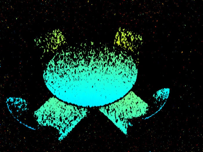
Figure 2. Ambient sunlight can reduce depth quality.
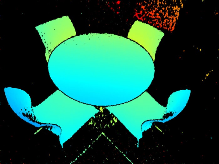
Figure 3. The Low Ambient Light preset helps to improve depth when ambient sunlight exists.
Non-optimal Surfaces
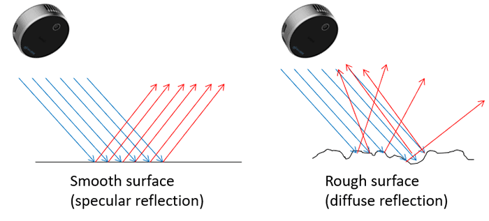
L515 works best on objects that have a reflective and matte surface resulting in a diffuse reflection. If a surface is too smooth and reflective (mirror finish) light hitting the surface at an angle will not reflect back to the camera as illustrated below. Comparatively rough surfaces allow some of the light to be reflected back to the camera and used to calculate distance.
Some material does not reflect much light at all which results in no depth data. An example of such material is darkly colored carpeting and some black plastics. This does not mean that dark carpet cannot be detected by the camera. It does mean that while a wooden floor may produce an excellent depth map at 5 meters distance, the dark carpet may not produce a good depth map until the distance from the camera reduces to 3 or 4 meters.
Configuring for Minimum Range
While the L515 is designed to provide highly accurate depth at longer distances, its LiDAR technology also gives excellent, high resolution depth at closer distances. If the camera will be used for a short range application it is recommended to use the Short Range preset. This preset reduces the laser power and receiver gain allowing the camera to be positioned near objects while reducing the likelihood of receiver oversaturation. As noted in the tradeoff table above, lowering the laser power and receiver gain does reduce the maximum range of the camera.
Configuring for Maximum Range
The maximum range of the L515 depends on laser power, receiver gain, object material, and ambient light. The camera can achieve its maximum possible range with a highly reflective object in a space with no ambient light.
If achieving the maximum range from the camera is the primary goal, the Max Range preset and QVGA resolution is recommended. The Max Range preset sets the laser power and receiver gain to maximum values. This gives the best opportunity for the light projected to be reflected at a far distance and received by the camera. QVGA resolution allows more time for integration of each pixel compared to VGA and XGA and more integration time means that lower powered reflected light can be detected and used.
Ambient sunlight will have a significant effect on range. An increase in the ambient light requires the camera to work harder in separating the ambient light noise from the light generated by the camera. The strength and quality of the light generated by the camera decreases with range. This is true of any light source and can be easily observed as light is strongest nearest a lamp and becomes weaker the further one moves away from the lamp. This is also true of the light projected by the L515 and therefore, the further the light travels, the weaker it becomes and the smaller the received signal will be.
The L515 is projecting the laser IR beam outwards in a spherical shape although it displays depth as a plane. Let’s consider for example an application that is scanning a wall at 9m distance from the camera. In this case, the distance from the camera at the center of the sphere is 9m. The light that travels to the edge of the field of view horizontal to the center of projection however, is 10.98m. This is calculated as 9m divided by cos35° (horizontal field of view is 70°). The corner of the FOV is even further away. Since the max range specified for the camera is 9m, one should expect reduction in plane projected FOV when approaching that range. L515 supports 10% ROI at 9m due to that specific reason.
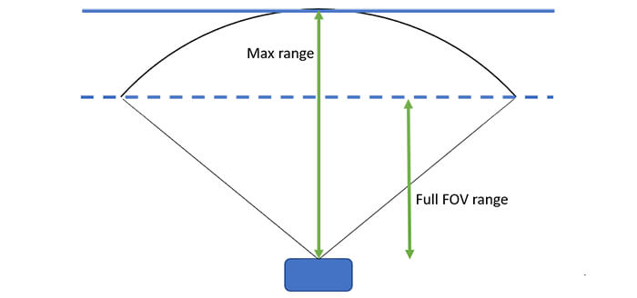
Figure 4. Illustrates maximum range versus full FOV max range.
The following images illustrate what the depth map may look like at different distances.
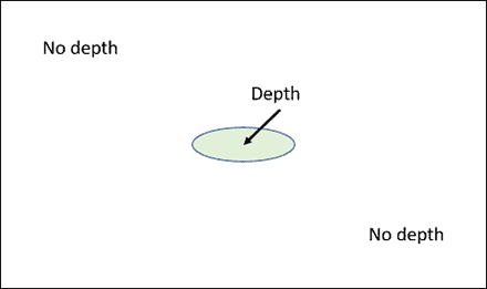
Figure 5. Depth is only available in center of frame at Max range.
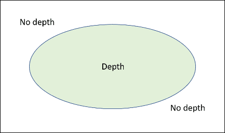
Figure 6. At a distance between Max range and Full FOV range, depth fills portion of the frame.
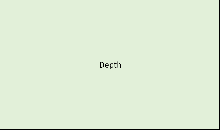
Figure 7. Depth available over entire frame at Full FOV range.
Another point to consider is the signal to noise ratio. L515 can work in very low SNR situations as it operates using coded IR light. Ambient light or reduction in reflectivity will have an impact on the SNR however. The SNR to range calculation can be simplified as the square root of the SNR reduction. For example, our video below demonstrates 9m range indoors with a white wall. Assuming the white wall has 90% reflectivity, if the camera is pointed at a black wall that has 15% reflectivity, the returned light signal strength will be 6 times lower. This means the SNR is 6 times higher with the 90% reflective wall. To calculate the range at the 15% reflective wall, take the square root of 6 which is 2.44 (square root(6) = 2.44) and divide the 9m distance by 2.44 to get the expected range. In result, the camera will be able to detect the black wall at 3.6m (9/2.44 =3.6).
In the case of high frequency light sources (e.g. >1MHz), which may be found in some time of flight (ToF) cameras, the result is the same as lowering reflectivity in the scene. It is suggested to not operate ToF cameras near the L515 LiDAR Camera for optimal results.
Example of 9-meter depth
This video features the L515 operating at 9 meters. You may also download the corresponding .bag file here. The .bag file can be opened and run in the RealSense Viewer tool. The example scene uses a mix of LED and fluorescent lighting and has objects at various distances. The furthest point in the scene is approximately 9.3 meters from the camera in the center of the frame. The L515 is configured with a laser power of 100 and receiver gain of 9 which matches the settings of the “max range” present available in the Intel RealSense SDK 2.0.
For additional information on how to get the best performance from your Lidar Camera L515 and the Intel RealSense SDK, please refer to the L515 User Guide.
Subscribe here to get blog and news updates.
You may also be interested in
In a three-dimensional world, we still spend much of our time creating and consuming two-dimensional content. Most of the screens
A huge variety of package shapes, sizes, weights and colors pass through today’s e-commerce fulfilment or warehouse distribution centers. Using