

How-to: Getting IMU data from D435i and T265
With the introduction of the Intel® RealSense™ Depth Camera D435i and Tracking Camera T265, the librealsense SDK has been enhanced to support and effectively utilize the functionality provided by these new sensors.
Core Capabilities
The D435i and T265 models sport a Bosch BMI055 6-axis inertial sensor. Inertial Measurement Units (IMU) are sensors which allow measurement of both directional movement and rotation. The sensor is comprised of triaxial 12bit linear acceleration and triaxial 16bit angular velocity gyro sensors.
The D435i depth camera generates and transmits the gyro and accelerometer samples independently, as the inertial sensors exhibit different FPS rates (200/400Hz for gyro, 63/250Hz for accelerometer). Each IMU data packet is timestamped using the depth sensor hardware clock to allow temporal synchronization between gyro, accel and depth frames.
The T265 tracking camera utilizes the same IMU sensor as the D435i. However, unlike the D435i, which delivers the raw IMU data directly to the host PC, the T265 redirects IMU readings into an Intel® Movidius™ Myriad™ 2 Vision Processing Unit (VPU). The inertial sensor data is also complemented by video from two fisheye monochrome sensors that are fed into the VPU as well.
The VPU employed with T265 is capable of fusing inertial and video sensors to produce a reliable and persistent six degrees of freedom (6DOF) pose, offloading the CPU-intensive calculations from the host PC.
The following table summarizes the features and capabilities of the two devices (T265 vs D435i):
| Feature | D435i | T265 | Notes |
| IMU Sensor | Bosch BMI055 | Bosch BMI055 | |
| IMU Bias&Scale Correction | Not provided1 | Yes | 1Feasible with SDK suite (D435i, T265) |
| 3DOF acceleration | 62.5/250 Hz | 62.5Hz | meter/sec2 |
| 3DOF gyro | 200/400 Hz | 200Hz | radian/sec |
| 6DOF Pose | N/A | HW-generated at 262 Hz | Each sample contains: – Position vector [xyz] – Orientation quaternion [xyzw] – Linear velocity and acceleration vectors – Angular velocity and acceleration vectors – Tracking confidence [hi/med/low] |
| Additional sensors | Depth/Left+Right IR/RGB identical to D435 | Two Fisheye sensors at 848X800 resolution/ 30FPS | |
| Relocalization | N/A | Yes | |
| Sensors orientation | Aligned to depth | VR-Standard | See Tracking Sensor Origin and CS |
Tracking Sensor Origin and Coordinate System (CS)
Intel RealSense D435i
The IMU sensor location and orientation relative to the depth sensors are conveniently embedded into the sensor’s extrinsic data. In order to align and them with SDK-wide established orientation convention using the depth sensor as CS origin, each IMU sample is multiplied internally by the extrinsic matrix.
The resulted orientation angles and acceleration vectors share the coordinate system with the depth sensor.
1. The positive x-axis points to the right.
2. The positive y-axis points down.
3. The positive z-axis points forward
The angles are also compatible with OpenCV convention for pinhole camera model.
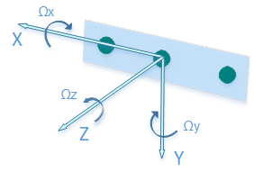
Intel RealSense T265
To aid AR/VR integration, the TM265 tracking device uses the defacto VR framework standard coordinate system instead of the SDK standard:
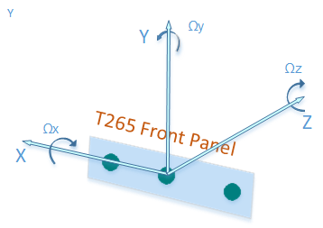
1. Positive X direction is towards right imager
2. Positive Y direction is upwards toward the top of the device
3. Positive Z direction is inwards toward the back of the device
The center of tracking corresponds to the center location between the right and left monochrome imagers on the device.
Device calibration
The IMU sensor does not include internal calibration, which may manifest itself with non-zero angular velocities produced at idle mode and the gravity (accel) force measured being not equal to 9.80665 m/s2. In order to rectify those inaccuracies, the T265’s IMU sensor is calibrated in the production line.
For D435i the IMU sensor is not calibrated, hence a free calibration tool is available as as part of the SDK. Running the calibration routine will calculate IMU intrinsic covariance and zero offsets, and then store them on device’s NVRAM for later use in SDK. The depth<->IMU sensor extrinsic (rigid body transformation) is precalculated based on mechanical drawings and cannot be modified. When initialized, the SDK will query the device for the existence of the IMU calibration data, and if present – apply it to the raw IMU samples produced by the device.
Integration with the SDK
The following librealsense tools and demos are IMU and tracking-ready:
– rs-capture – 2D Visualization.
– rs-enumerate-devices – list the IMU and tracking profiles (FPS rates and formats).
– rs-data-collect – Store and serialize IMU and Tracking (pose) data in Excel-friendly csv format. The tool uses low-level sensor API to minimize software-imposed latencies. Useful for performance profiling.
– realsense-viewer – Provides 2D visualization of IMU and Tracking data. 3D visualization is available for Pose samples:
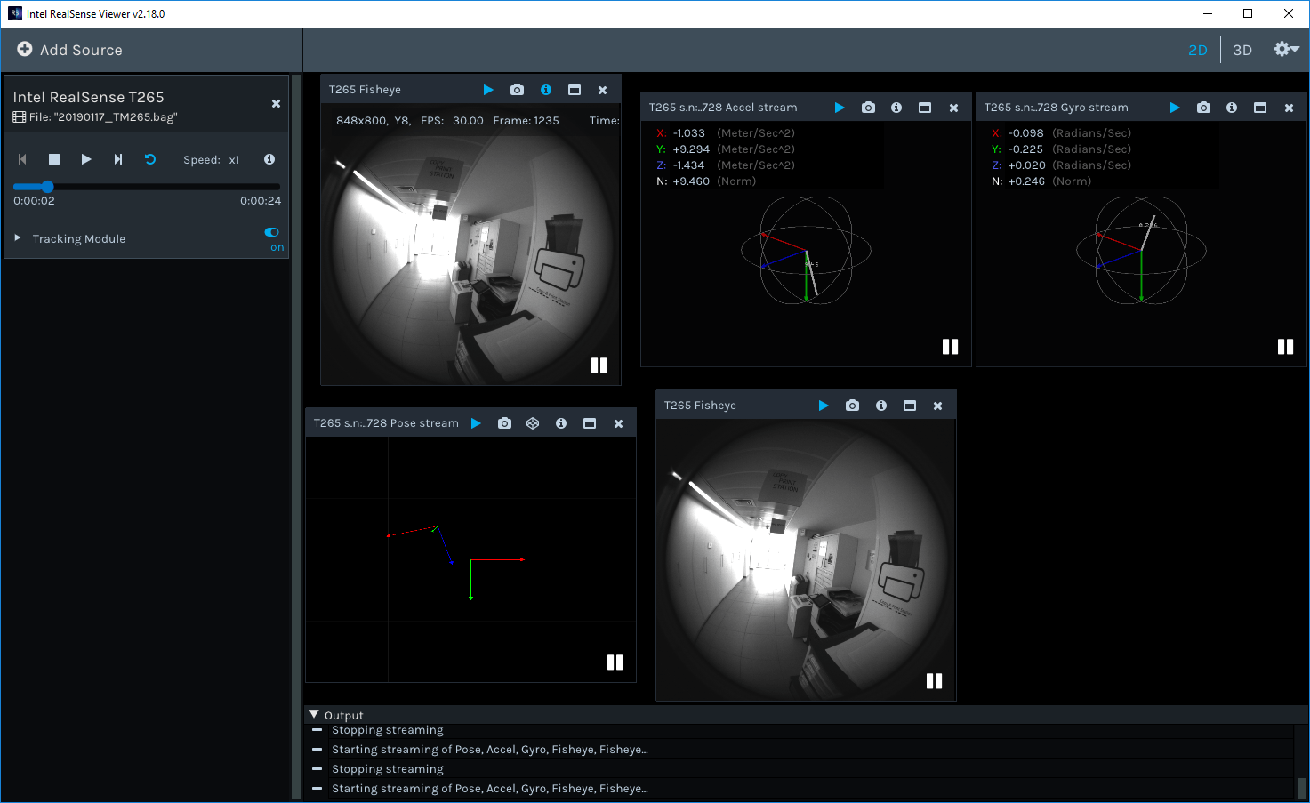
![]()
The IMU and Tracking data streams are fully compatible with SDK’s embedded recorder utility.
API
The IMU and tracking sensors are treated by the SDK like any other supported sensor. Therefore the sensor access and invocation API calls are similar to those of the depth/rgb sensors of D400 and SR300. See our GitHub for more details.
Supported platforms
The IMU and tracking sensors are currently supported on Windows and Linux* OS. Linux OS requires the kernel patches to applied either manually or via the librealsense2-dkms package.
macOS* and Android* support is planned but there is still no firm timeline.
Subscribe here to get blog and news updates.
You may also be interested in
“Intel RealSense acts as the eyes of the system, feeding real-world data to the AI brain that powers the MR
In a three-dimensional world, we still spend much of our time creating and consuming two-dimensional content. Most of the screens