

Best Known Methods for Optimal Camera Performance over Lifetime
| D415 D435 D435i D455 | Download PDF |
Revision 1.1
Contents
- Introduction
1.1 Purpose and Scope of This Document
1.2 Organization - Overview
2.1 Definitions
2.2 Tools Needed for Integration Process
2.3 Configuration Considerations
2.4 Camera Integration - Keep Optimal Camera Performance over Lifetime
3.1 Camera Performance
3.2 Calibration Types
3.3 When to Use Each Calibration
3.4 Self Calibration
3.4.1 On-Chip Calibration
3.4.2 Tare Calibration
3.5 Dynamic Calibration
3.6 OEM Calibration
3.6.1 Launch OEM Calibration Tool
3.6.2 Start the Process
3.6.3 Capture Images from Two Viewpoints
3.6.4 Running Calibration Algorithm
3.7 Depth Quality Tool (DQT) - Conclusion
Figures
- FIGURE 2-1. CAMERA USB CONNECTION
- FIGURE 2-2. REALSENSE VIEWER DEPTH AND RGB STREAMS
- FIGURE 2-3. REALSENSE VIEWER ON-CHIP CALIBRATION
- FIGURE 2-4. HEALTH-CHECK NUMBER
- FIGURE 3-1. REALSENSE VIEWER ON-CHIP CALIBRATION
- FIGURE 3-2. HEALTH-CHECK NUMBER
- FIGURE 3-3. TARE CALIBRATION
- FIGURE 3-4. TARE CALIBRATION FROUND TRUTH
- FIGURE 3-5. DYNAMIC CALIBRATION TARGET
- FIGURE 3-6. DYNAMIC CALIBRATION
- FIGURE 3-7. DYNAMIC CALIBRATION SUCCESSFUL
- FIGURE 3-8. OEM CALIBRATION ICON
- FIGURE 3-9. OEM CALIBRATION REALSENSE™ DEVICE DETAILS
- FIGURE 3-10. OEM CALIBRATION PROCESS START
- FIGURE 3-11. PRE-DEFINED POSITIONS
- FIGURE 3-12. MARKED POSITION VIEWPOINT #1 (CLOSE POSITION #1)
- FIGURE 3-13. MARKED POSITION VIEWPOINT #2 (FAR POSITION #2)
- FIGURE 3-14. CALIBRATION ALGORITHM RUN WINDOW & UPDATE
- FIGURE 3-15. OEM CALIBRATION SUCCESS OR FAIL
- FIGURE 3-16. DEPTH QUALITY TOOL
- FIGURE 3-17. DEPTH QUALITY TOOL FLOW
Tables
- TABLE 2-1. TERMINOLOGY LIST
- TABLE 2-2. INTEGRATION PROCESS TOOLS LIST
- TABLE 2-3. INTEGRATION CONSIDERATIONS
- TABLE 3-1. CALIBRATION TYPES
- TABLE 3-2. HEALTH SCORE MEANING
- TABLE 3-3. ON-CHIP CALIBRATION HEALTH CHECK RESULTS NEXT STEPS
- TABLE 3-4. OEM CALIBRATION POSITION DETAILS
Revision History
| Revision Number | Description (Initial Doc Flow) | Revision Date |
|---|---|---|
| 001 | Initial Release | February 2021 |
| 002 | Update Tare Calibration | March 2021 |
1. Introduction
1.1 Purpose and Scope of This Document
Intel RealSense™ cameras leave the factory meeting all datasheet specifications. Due to shipping, handling, or adverse environments the quality of depth accuracy may be impacted. The purpose of this document is be a Reference Guide for Intel® RealSense™ Stereo Depth Cameras to ensure the positive Out of the Box (OOB) experience and keep the optimal performance over the lifetime. This document references other documents but will cover key steps in its guidance.
It is not in the scope of this document to discuss the details of depth or calibration deeply. Additionally, modules are out of scope of this documentation but described to ensure it is clear what is out of scope.
1.2 Organization
This document contains five main parts: definitions, tools, incoming, integration and outgoing considerations:
- Definitions – Overview of terminology.
- Tools – List of tools and sites to leverage the information in this document.
- Unboxing Steps – Steps and considerations when unboxing a depth camera.
- Verifying the Health of Camera – How to know if the camera is functioning correctly.
- Camera Improvement Options – Steps and considerations after mounting or integration depth products.
2. Overview
2.1 Definitions
Table 2-1. Terminology List
| Term | Definition | Comment / Access |
|---|---|---|
| Module
(Optical Head) |
Stereo Module without a computing engine or housing.
|
Available at: https://store.intelrealsense.com/ or you can contact an Intel® RealSense™ Sales Representative. |
| ASIC Card | Depth computing subsystem that is paired with a module to activate compute vision processing.
|
You can buy an ASIC card as a bundle with a module at: https://store.intelrealsen se.com/ or you can contact an Intel® RealSense™ Sales Representative. |
| Camera | A module and ASIC Card in a “peripheral-like” housing.
|
Available at: https://store.intelrealsense.com/ or you can contact Intel® RealSense™ Sales Representative. |
| Depth Quality Tool
(DQT) |
SW tool that measures depth camera quality.
|
https://www.intelrealsense.com/sdk-2/ |
| Calibration | Calibration is a method to get the Intel® RealSense™ module or camera to behave as expected. | There are three types of calibration processes that will be discussed in this document. |
2.2 Tools Needed for Integration Process
Table 2-2. Integration Process Tools List
| Tool | Locations | Considerations |
|---|---|---|
| Intel® RealSense™ SDK | https://www.intelrealsense.com/sdk-2/ | |
| Intel® RealSense™ Self Calibration | https://www.intelrealsense.com/self-calibration-for-depth-cameras/ | The tool is in our SDK. This is a link to the whitepaper on Self-Calibration. |
| Intel® RealSense™ Dynamic Calibration | https://dev.intelrealsense.com/docs/calibration
|
|
| Intel® RealSense™ OEM Calibration | Access comes with a target. V shape OEM target: https://store.intelrealsense.com/buy-intel-realsense-d400-cameras-calibration-target.html
|
Highly recommended post module or camera integration. This tool is targeted for factory customers, but any user could benefit. |
| Mounting and Integration Guidelines | https://dev.intelrealsense.com/docs/intel-realsense-d400-series-product-family-datasheet | At time of publication this was located in section 7 of the datasheet. |
2.3 Integration Considerations
Table 2-3. Integration Considerations
| Considerations | Camera | Module |
|---|---|---|
| Integration Requirements | Mounting Only | Mounting, routing, thermal and enclosure must be completed. |
| Calibration Automatically Required | No. Expected to work OOB. | Yes. Post integration. |
Note: All information (such as mounting and routing) for these considerations are in the https://dev.intelrealsense.com/docs/intel-realsense-d400-series-product-family-datasheet.
2.4 Camera Integration
Intel® RealSense™ Cameras D400 series camera is a plug-and-play USB3.1 high quality stereo depth camera. USB 2.0 is supported also. Just simply follow the mounting guidelines in the datasheet and gain access to the SDK and depth streaming will be enabled. Intel® RealSense™ SDK 2.0 is a cross-platform library for Intel® RealSense™ depth cameras. It is an open source SDK and can be accessed at https://www.intelrealsense.com/sdk-2/.
2.4.1 Camera Incoming Quality Considerations
- Connect the camera to a host system. This requires all components in Figure 2-1. Note: an USB-C to USB-C cable is also acceptable if the host has a USB-C port.
Figure 2-1. Camera USB Connection
- To activate the camera please use the Intel® RealSense™ SDK. The SDK can be found at: https://www.intelrealsense.com/sdk-2/.
- Once you download and install the SDK, there should be two tools installed on your Windows® 10 based system. The RealSense™ Viewer and The Depth Quality Tool for RealSense™ Cameras
- Launch the Viewer (icon below) and enable your Stereo Module. The default is off. You can also enable your RGB camera although the focus of this document is depth.
- Once you enable the Stereo Camera a very colorful depth map should appear to the right of the controls. Blue should be objects “close” to the RealSense™ Camera and red will be the objects far away. That is the default color scheme.
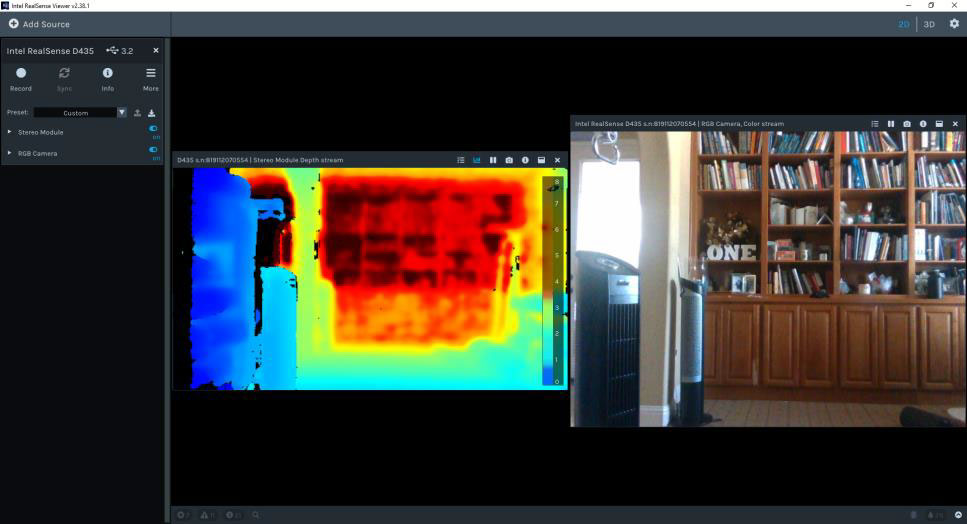
Figure 2-2. RealSense Viewer Depth and RGB Images
- Next, Intel suggests you verify the quality. Intel RealSense™ has a locally running calibration tool called Self-Calibration that runs directly on the RealSense™ device. In the Viewer it is called “On-Chip Calibration.” This calibration method improves the camera’s depth quality, but also gives information on the current health level of the camera. Intel suggests you run this tool and verify that the camera health is good. It is in the “more” section of the viewer.
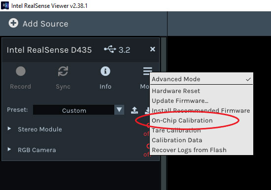
Figure 2-3. RealSense Viewer On-Chip Calibration
- After you run On-Chip Calibration you will get “Health-Check” number. For next steps see Error! Reference source not found. Table 3-3. On-Chip Calibration Health Check Results Next Steps
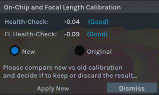
Figure 2-4. Health-Check Number
If you see the Health-Check and FL-Health-Check numbers are all “Good”, you are ready to go!
3. Keep Optimal Camera Performance over Lifetime
3.1 Camera performance
All RealSense camera sensor modules are built from factory to be extremely sturdy, encased in laser-fused steel cages, with the intent of maintaining calibration and performance over their lifetime. However, conditions can occur that lead to degradation over time, such as exposure to extreme temperature cycling, or excessive shock and vibe. Whatever the cause, Intel provides a set of tools to recalibrate cameras back to their pristine factory condition and keep the best performance over lifetime. These tools include “Self-Calibration”, “Dynamic Calibration, and “OEM calibration”.
3.2 Calibration Types
To keep Intel® RealSense™ Cameras optimal performance, Intel® RealSense™ offers three types of calibration, namely, Self Calibrtion, Dynamic Calibration, and OEM Calibration. For module integration and factory environments, Intel strongly recommends the purchase of an OEM calibration target and learning the accompanying tools. Please work with the Intel Sales and Support teams to gain access. Table 3-1 are the considerations when selecting a calibration type.
Table 3-1. Calibration Types
| Characteristics | Self-Calibration | Dynamic Calibration | OEM Calibration |
|---|---|---|---|
| Calibration Execution Engine | Intel® RealSense™ vision processor D4 | External PC/SOC | External PC/SOC |
| Reference Target | On-Chip Calibration – No Focal Length Calibration – No Tare Calibration – Optional: Use ground truth or target |
Printed A4 target or smart phone (Google or Apple) target (can be downloaded online) | V shape OEM target: https://store.intelrealsense.com/buy-intel-realsense-d400-cameras-calibration-target.html |
| Typical Time to Completion | Less than 30 seconds | 40 seconds (depth only) 80 seconds (depth + RGB) – 10-20 seconds device ramp up time included |
30 seconds – 10 seconds device ramp up time included |
| Calibrated Parameters | Intrinsic or extrinsic | Extrinsic only, but can cover some intrinsic shifts to a small degree | Both intrinsic and extrinsic |
| Calibrated Subsystems | Depth only | Depth and RGB | Depth and RGB |
3.3 When to Use Each Calibration
Self-Calibration is the the most convenient and easiest calibration for users. It can be used when you open the box – incoming quality validation. Or after the cameras are mounted on your devices in the field. The calibration is running inside the VPU chip inside the camera. It calibrates only depth camera.
Dynamic calibration can be executed either in lab or in the field. It requires a A4 printed paper target or a smart phone target. It calibrates both depth and RGB cameras.
OEM calibration is the most robust calibration method for Intel® RealSense™ stereo cameras. It requires a big V shape calibration target. It is used in the factory setup or in the lab. It is highly recommended if you purchase RealSense cameras modules and ASIC cards and build the camera enclosure yourselves. It will rectify all kinds of distorations introduced by mounting the modules into the new enclosures.
3.4 Self-Calibration
Self-Calibration includes two parts, namely On-Chip Calibration and Tare Calibration.
On-Chip Calibration is to minimize the noise. Tare Calibration is to improve the depth accuracy.

Figure 3-1. RealSense Viewer On-Chip Calibration
After you run On-Chip Calibration you will get “Health-Check” number.
Figure 3-2. Health-Check Number
Table 3-2. Health Score Meaning
| Health Score (ABS) | FL Health Score (ABS) | Score Meaning |
|---|---|---|
| 0<HC<0.25 | 0<HC<0.15 | Pass |
| 0.25<HC<0.75 | 0.15<HC<0.75 | Help |
| 0.75<HC | 0.75<HC | Fail |
3.4.1 On-Chip Calibration
Table 3-3. On-Chip Calibration Health Check Results Next Steps
| Health Check Value (Absolute Value) |
FL Health Check Value (Absolute Value) |
Next Step | Notes |
|---|---|---|---|
| 0.25 or less | 0.15 or less | Do nothing. | Changes can be accepted, but it is not required. |
| Between 0.25 and 0.75 | Between 0.15 and 0.75 | Accept the changes in Self Calibration. | Run Self Calibration again and verify the absolute value of the health check. |
| 0.75 or greater | 0.75 or greater | Recalibrate the camera using Dynamic Calibration or OEM Calibration. | Note: either Dynamic or OEM Calibration should help improve the camera’s performance, but OEM Calibration is the most robust and requires the most equipment. |
Note1: On-Chip Calibration works best when the camera is pointed at scenes with details.
Note2: These numbers are guidelines and not absolutes. It is important for each camera to be validated as an acceptable depth map for the desired usage as depth map requirements vary based on usage.
3.4.2 Tare Calibration
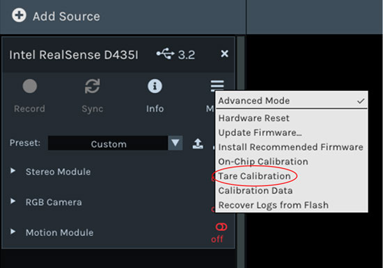
Figure 3-3. RealSense Viewer Tare Calibration
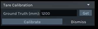
Figure 3-4. Tare Calibration Ground Truth
When you run the Tare Calibration, you will need to provide the ground truth. A laser range finder is a good tool to provide a good ground truth.
3.5 Dynamic Calibration
Dynamic Calibration is a good calibration option if Self-Calibration does not resolve camera quality issues. The Dynamic Calibration Tool can be found at same site as the quick start guide: https://dev.intelrealsense.com/docs/d400-dynamic-calibration-quick-start-guide. It is one of the tools to the left of the page. Due the extensive capabilities of Dynamic Calibration a target is suggested. There is a target-less solution, but Intel suggests a target be used. This document will assume a target is used. While the tool offers an excellent step by step demo the steps for dynamic calibration are:
- Choose a target. A target can be printed or done via a phone. Appendix C of the Dynamic Calibration Quick start guide can help with a target choice.
- The target must meet very specific criteria for it to be effective. The paper target today is on 8.5×11 paper and there are specific phones that can be targets. The current version of the tool will give specifics on the limits.
- The target must be between 600-850mm away and the bars must be placed vertically. Example placement below.
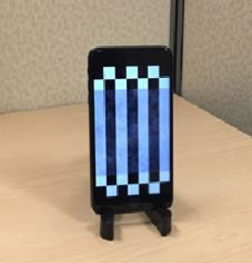
Figure 3-5. Dynamic Calibration Target
- Connect the device and start calibration.
- The first phase of calibration is Rectification where the left and right image are rectified and prepares the device to fix any scale errors. See Figure 3-6
- Execute the Scale Phase where any scale errors are resolved by moving the camera around to specific locations that are guided to you by the app. There is an RGB phase next.
- This paper is focused on depth, so it is not covered, but it is functionally very similarly to depth.
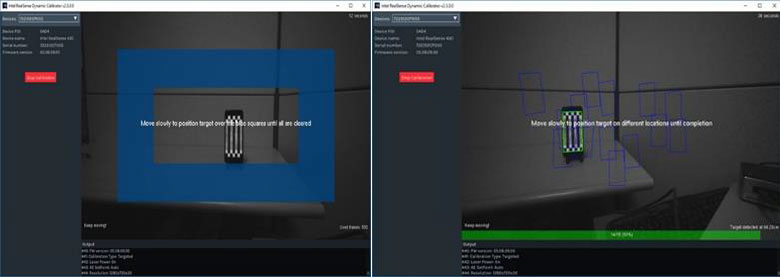
Figure 3-6. Dynamic Calibration
With Dynamic Calibration the camera must be aligned with the target initially and then moved to multiple locations. This must be done with depth and RGB calibration. Please follow the User Guide and application.
The result should be a successful calibration as shown in Figure 3-7.
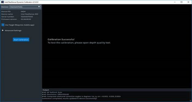
Figure 3-7. Dynamic Calibration Successful
- While there will be a calibration successful message, Intel suggests that DQT be run again to verify that the camera functions properly. If DQT reports that the camera is functioning within specification, then the camera is ready to use.
- If DQT still gives poor results, then it is suggested that a OEM calibration is needed. See section 3.6 for the OEM Calibration Process. This is Intel’s most robust calibration tool and can resolve even very distorted cameras. If you don’t have access to OEM Calibration yet please contact Intel support teams at: https://www.intelrealsense.com/support/. If you are an NDA customer, please use your Zendesk support portal account.
3.6 OEM Calibration Process
3.6.1 Launch OEM Calibration Tool
Locate the “OEM Calibration Tool” app icon on desktop. This application is available once you buy the target from Intel. The target is located at: https://store.intelrealsense.com/buy-intel-realsense-d400-cameras-calibration-target.html. Intel does not share the software without the target to ensure there is no confusion in the calibration process.
Figure 3-8. OEM Calibration Icon
3.6.2 Start the Process
Double click to launch the tool. All connected Intel® RealSense™ Camera D400 series Depth Camera devices will be listed in the drop-down combo box. The list is presented with each device’s serial number. If all devices are not listed, use the refresh button to refresh the list.
Choose the desired device to be calibrated from the list. Details of this device include its serial number, SKU and Firmware version. This ensures the right device is selected in case multiple cameras are connected to your host system.
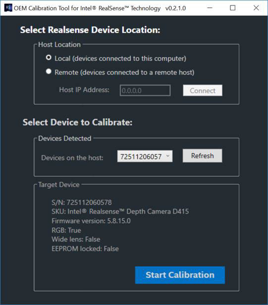
Figure 3-9. OEM Calibration RealSense™ Device Details
Once the correct device is selected, click the “Start Calibration” button to start the calibration process. A window with live streaming appears. The SKU, FW version and serial number of the device is displayed in the top left and right corners of the Window. Wait a few seconds for the device to warm up and get ready for calibration.
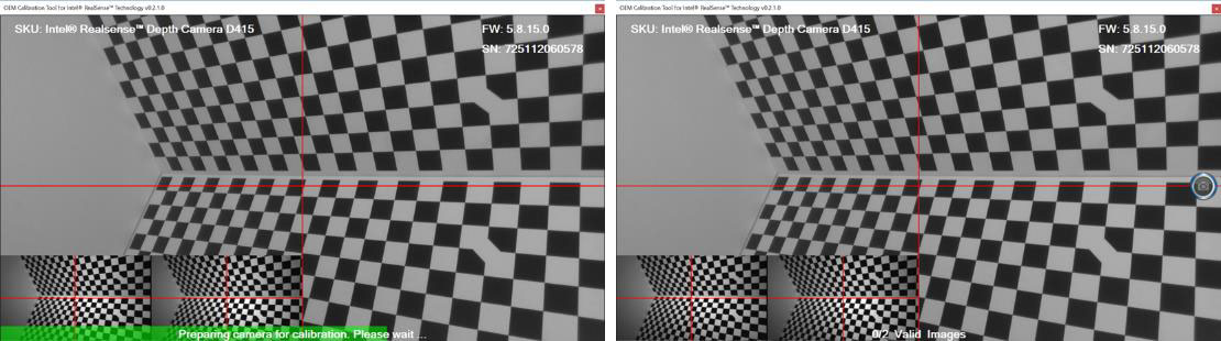
Figure 3-10. OEM Calibration Process Start
Once the camera finishes warming up, a capture button appears on the right side of the Windows*. In the next steps, user will need to move the device to the two pre-defined locations and use this button to capture images for calibration.
3.6.3 Capture Images from Two Viewpoints
Images from two viewpoints from pre-defined positions are required for the OEM calibration algorithm.
Table 3-4. OEM Calibration Position Details
| Placement | Description |
|---|---|
| Position #1 | Distance Measurement: 60cm (+/- 1mm) Angle Measurement: 17deg (+/- .5 deg) – Right of midline |
| Position #2 | Distance Measurement: 85cm (+/- 1mm) Angle Measurement: 17deg (+/- .5 deg) – Left of midline |
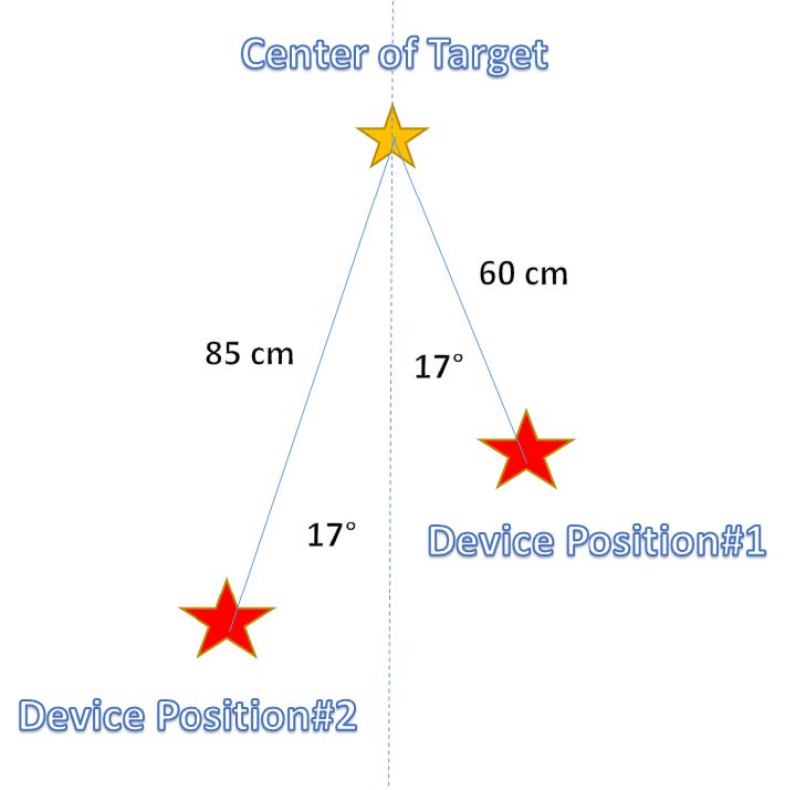
Figure 3-11. Pre-defined Positions
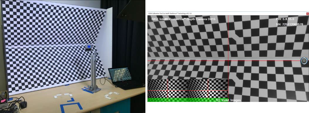
Figure 3-12. Marked Position Viewpoint #1 (Close Position #1)
Press the capture button at the right side to capture the image for this position. The software verifies the image and either accepts or rejects it. If it’s accepted, it will display a green progress bar at bottom and the status message will be changed to “1/2 Valid Images”. If it’s rejected, then no progress will be made, and a red error message will appear on screen and instruct user to recapture image at this position.
Once the image for position #1 is successfully captured, move the camera to position #2.
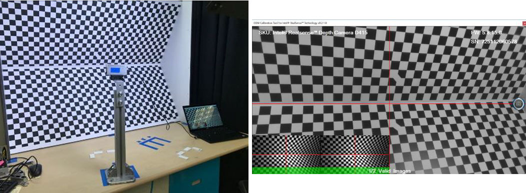
Figure 3-13. Marked Position Viewpoint #2 (Far Position #2)
Repeat the process from Position #1
3.6.4 Running Calibration Algorithm
Once the images from the two viewpoints are captured, the OEM Calibration Tool will automatically start compute of the calibration algorithms can usually takes 30 seconds.
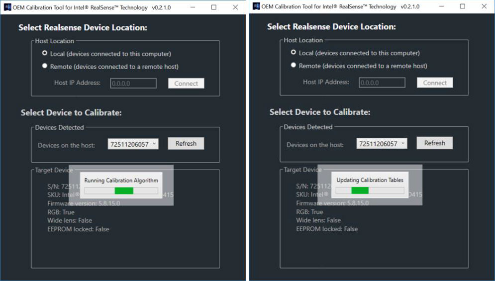
Figure 3-14. Calibration Algorithm Run Window & Update
A message box will appear to indicate a calibration pass or fail.
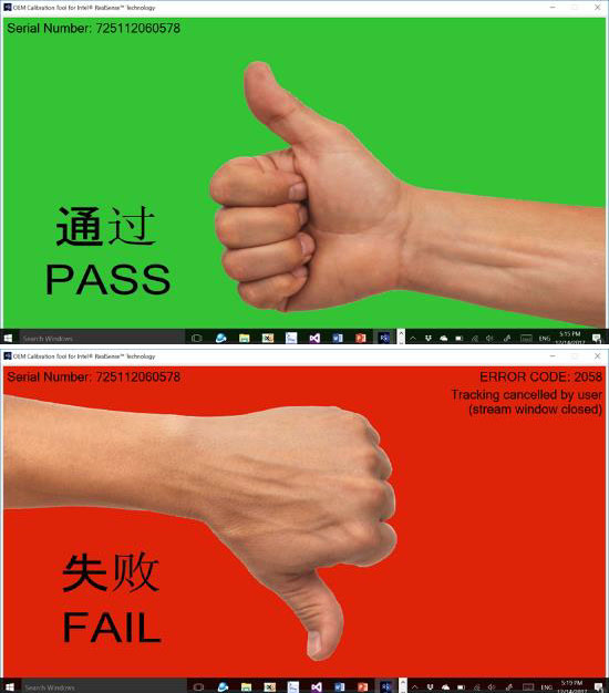
Figure 3-15. OEM Calibration Success or Fail
If the calibration fails during any of these steps, it will display an error message box. In that case, user will need to execute this process again. Intel suggests on executing OEM calibration up to three times. If failure continues then we suggest working with Intel support teams. If the camera passes OEM calibration, Intel suggest that DQT is executed again to ensure that the Intel camera is functioning properly. If the camera passes DQT then it is ready to use. If not then contact your support team at: https://www.intelrealsense.com/support/. If you are an NDA customer, please use your Zendesk account.
3.7 Depth Quality Tool (DQT)
This application allows you to test the camera’s depth quality, including: Z-Accuracy, Sub-Pixel and Z RMS errors (spatial noise) and Fill Rate. You should be able to easily get and interpret several of the depth quality metrics, or record and save the data for offline analysis.
Once the RealSense™ SDK is installed The Depth Quality Tool (DQT) is also installed. Launch the DQT (icon below).
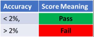
The Depth Quality Tool measures the cameras depth accuracy as reported in the z plane to match geometric location markers of x (horizontal), y (vertical) and z (depth). The tool requires an accurately known distance (ground truth) to be entered by the user to ensure the z-accuracy is correct. The more accurate the ground truth the more trustworthy the results of z-accuracy are in the depth quality. Do not underestimate the difficulty of imputing a good ground truth. A laser range finder is a good method. Intel also suggests that ground truth is near the specification of the camera. For example, z-accuracy specification D435 is 2% accuracy at 2 meters. This means a distance exactly 2 meters away would measure between 1.96 meters and 2.04 meters on a camera that is functioning properly. Most RealSense™ Depth Cameras commit to 2% accuracy at 2 meters. The newly released D455 commits to 2% accuracy at 4 meters. The fill rate should be equal or greter thn 99%. The RMS error should be equal or less than 2%.The temporal noise should be equal or less than 1%.
The DQT will give clear placement instructions to yield the most accurate results. If the accuracy is less than the committed specification for your camera then it is ready to use. If the accuracy is greater than the specification, for example on D435 it is 4.8% at 2 meters then go to section Dynamic Calibration3.5.
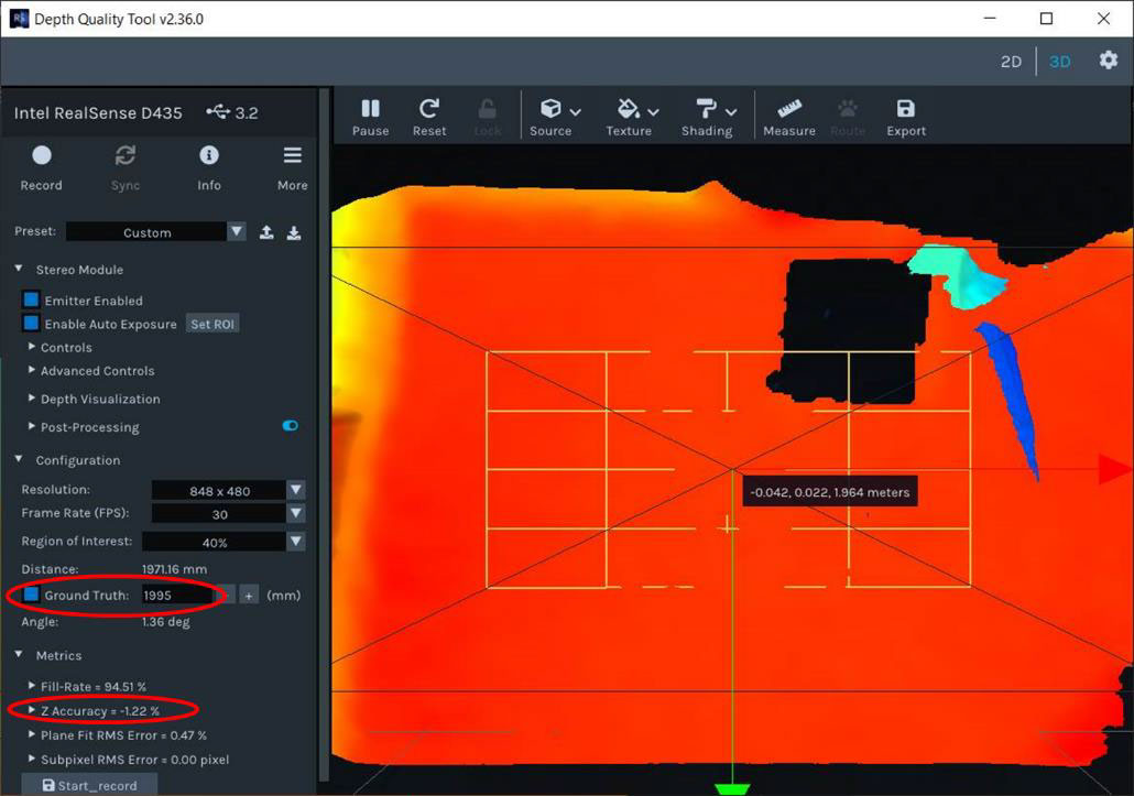
Figure 3-16. Depth Quality Tool
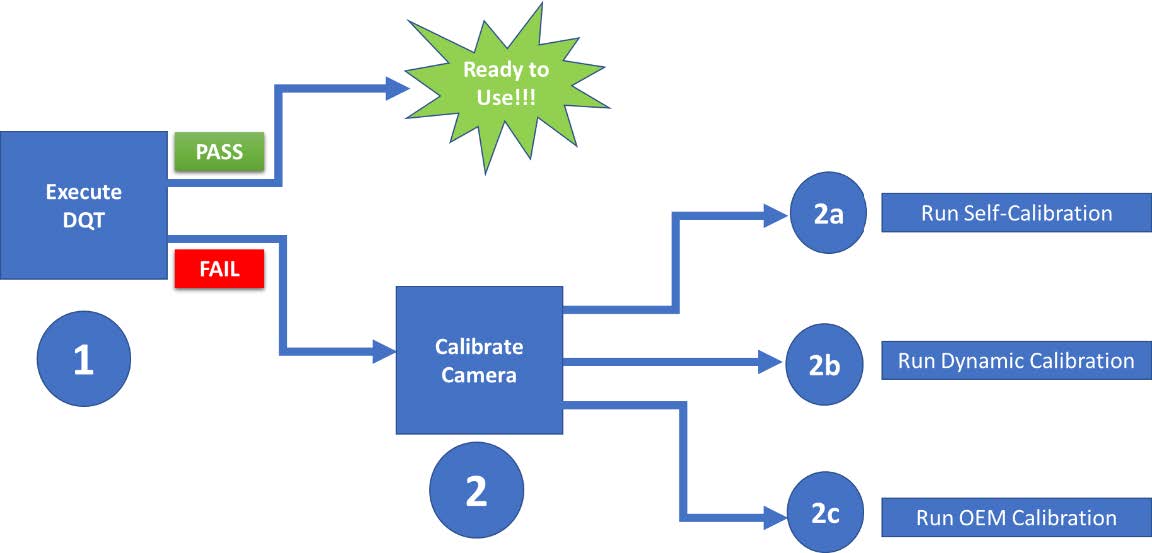
Figure 3-17. Depth Quality Tool Flow
Note: This is the complete flow for DQT, but if Self-Calibration has already been run then move to step 2b
Historically, Intel® RealSense™ Cameras quote the accuracy to be less than 2% error at 2 meters. The D455 specification is 2% at 4m. As stated earlier, the DQT is best when the measurement distance is very close to the specification range of the cameras.
4. Conclusion
Intel® RealSense™ Depth Camera products are robust and ready to use as a great solution for many compute visions challenges. Additionally, while this document has details on calibration techniques and product specs it is not comprehensive. Please ensure to reference the documents mentioned in the tools section of this document as well as the wealth of information on https://www.intelrealsense.com/.
INFORMATION IN THIS DOCUMENT IS PROVIDED IN CONNECTION WITH INTEL PRODUCTS. NO LICENSE, EXPRESS OR IMPLIED, BY ESTOPPEL OR OTHERWISE, TO ANY INTELLECTUAL PROPERTY RIGHTS IS GRANTED BY THIS DOCUMENT. EXCEPT AS PROVIDED IN INTEL’S TERMS AND CONDITIONS OF SALE FOR SUCH PRODUCTS, INTEL ASSUMES NO LIABILITY WHATSOEVER AND INTEL DISCLAIMS ANY EXPRESS OR IMPLIED WARRANTY, RELATING TO SALE AND/OR USE OF INTEL PRODUCTS INCLUDING LIABILITY OR WARRANTIES RELATING TO FITNESS FOR A PARTICULAR PURPOSE, MERCHANTABILITY, OR INFRINGEMENT OF ANY PATENT, COPYRIGHT OR OTHER INTELLECTUAL PROPERTY RIGHT.
A “Mission Critical Application” is any application in which failure of the Intel Product could result, directly or indirectly, in personal injury or death. SHOULD YOU PURCHASE OR USE INTEL’S PRODUCTS FOR ANY SUCH MISSION CRITICAL APPLICATION, YOU SHALL INDEMNIFY AND HOLD INTEL AND ITS SUBSIDIARIES, SUBCONTRACTORS AND AFFILIATES, AND THE DIRECTORS, OFFICERS, AND EMPLOYEES OF EACH, HARMLESS AGAINST ALL CLAIMS COSTS, DAMAGES, AND EXPENSES AND REASONABLE ATTORNEYS’ FEES ARISING OUT OF, DIRECTLY OR INDIRECTLY, ANY CLAIM OF PRODUCT LIABILITY, PERSONAL INJURY, OR DEATH ARISING IN ANY WAY OUT OF SUCH MISSION CRITICAL APPLICATION, WHETHER OR NOT INTEL OR ITS SUBCONTRACTOR WAS NEGLIGENT IN THE DESIGN, MANUFACTURE, OR WARNING OF THE INTEL PRODUCT OR ANY OF ITS PARTS.
Intel may make changes to specifications and product descriptions at any time, without notice. Designers must not rely on the absence or characteristics of any features or instructions marked “reserved” or “undefined”. Intel reserves these for future definition and shall have no responsibility whatsoever for conflicts or incompatibilities arising from future changes to them. The information here is subject to change without notice. Do not finalize a design with this information.
The products described in this document may contain design defects or errors known as errata which may cause the product to deviate from published specifications. Current characterized errata are available on request.
Contact your local Intel sales office or your distributor to obtain the latest specifications and before placing your product order.
Copies of documents which have an order number and are referenced in this document, or other Intel literature, may be obtained by calling 1-800-548-4725, or go to: http://www.intel.com/design/literature.htm.
Code names featured are used internally within Intel to identify products that are in development and not yet publicly announced for release. Customers, licensees and other third parties are not authorized by Intel to use code names in advertising, promotion or marketing of any product or services and any such use of Intel’s internal code names is at the sole risk of the user.
Intel and the Intel logo are trademarks of Intel Corporation in the U.S. and other countries.
*Other names and brands may be claimed as the property of others.
Copyright © 2021, Intel Corporation. All rights reserved.
Subscribe here to get blog and news updates.
You may also be interested in
“Intel RealSense acts as the eyes of the system, feeding real-world data to the AI brain that powers the MR
In a three-dimensional world, we still spend much of our time creating and consuming two-dimensional content. Most of the screens