

How-To: A Simple Way to 3D Scan an Environment
In this How-To, we are going to share a simple way to 3D scan an environment that you can then visit and share with friends and family. This process will involve multiple steps and pieces of software, but should be relatively easy to follow.
What you will need:
- Intel® RealSense™ Depth Camera D415, D435, D435i or L515
- Microsoft* Surface tablet, Windows* laptop or compatible Android* device
- Dot3D Pro*
- Meshlab*
- Blender*
- Firefox*
- Optional – VR headset
Step One: Creating the scan
There are a number of 3D scanning applications out there that work with Intel RealSense Depth cameras, but in this case we’re choosing to use Dot3D Pro, because it’s very easy to use, and allows us to quickly create a good scan and export the file. For the purposes of this demo, we used a Microsoft Surface Pro 4 (gen 6), but any device compatible with Dot3D Pro will work. Using a tablet makes the process of scanning easier, but a laptop or even desktop with a long enough USB cable could also be used.
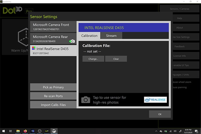
Once the camera is connected to the tablet (for this application, you must use a USB 3 cable and port), we open the software and select it within the settings window. From there, we can choose to create a new scan, and then simply select the “scan” icon to begin.
As you move around, the pixels from the camera feed will turn white, yellow and green. Green means that that area is fully scanned. For a fully water tight scan, you should spend more time moving around the small detail areas and filling in any holes. When choosing a location, you can choose an outdoor space, but try and avoid extremely bright sunlight as your resulting model may look inconsistent or you may have some issues accurately scanning the space. If you are using the L515 for your scan, you should only scan indoor spaces for best results. As you can see from our scan, there were some issues with a shiny black table – this sort of material is not easy to capture with a depth camera, so whenever possible avoid anything that is very dark and reflective if you can.
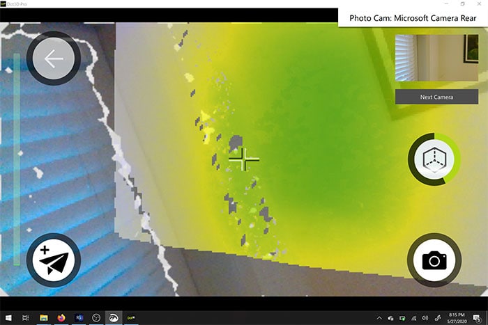
As you are moving through the space and doing as comprehensive scan as possible, you can also use the camera on your host device to take a high res RGB still that will be tied to the location you scanned it from – this can be used as later reference if you plan on working on your model in a 3D package like Blender or Maya.
Once you are happy with the scan, tap the scan button again to finish. From here, you should optimize the model. This may take a few minutes depending on the size of your scan.
Once optimized, save the scan as a .ply file.
Step 2: Converting to OBJ.
PLY files are a point cloud file, and can be used as is, for example, by uploading your PLY to sketchfab you can share the scan or view it in VR. However, if you want a bit more flexibility as to what you do with the file since PLY files are quite large, you may wish to convert it to a mesh. For this part of the process we are going to use Meshlab to convert the PLY to an OBJ.
Open Meshlab, and go to File> Import Mesh. Import the PLY file you exported in the last step.
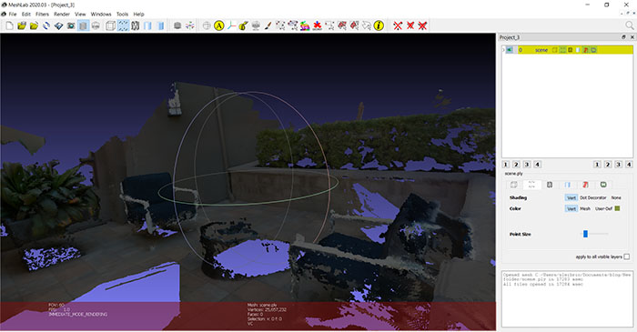
Meshlab showing imported mesh.
From here, we’re going to run a few operations to clean up the point cloud and turn it into a mesh. Depending on what your file looks like, you may want to spend some time playing around with the settings and deleting any extraneous vertices you didn’t want. Use the “Select Vertices” button on the top of the toolbar, and then select groups of vertices to delete using the “Delete the current set of selected vertices” tool.
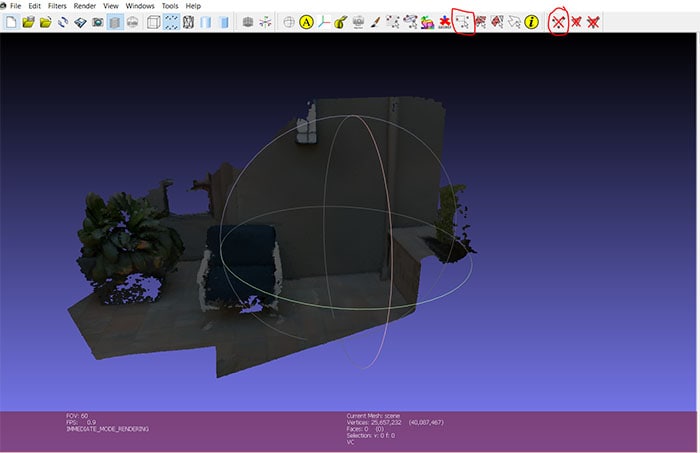
Cleaned up mesh with the two tools highlighted.
Next, go to Filters> Sampling > Poisson disk sampling >
On the settings, make sure you have “Base Mesh Subsampling” selected, and change the number of samples to tens of thousands – I chose 35,000. The higher the number here, the more refined your final mesh will be. Try not to go too high though, the number of triangles will affect how your final mesh operates in other programs and applications.
In the layer menu to the right, you should now see your original point cloud and the poisson sample. Delete the original mesh – we don’t need it anymore.
For the next step, go to Filters> Point set > Compute normal for point set. Change the neighbor number to 16 and run. This is trying to automatically determine which way each face will point.
Now choose Filters> Remeshing, Simplification and Reconstruction> Surface Reconstruction: Ball Pivoting. Click the up arrow on the world unit box by the “Pivoting Ball Radius” once – it should autofill an appropriate value. Apply, and we should now have a mesh instead of a point cloud. If you don’t like the resulting mesh, you can go back and repeat these steps with slightly different parameters.
So that we can take the color information we have along with us when we export from Meshlab, do the following steps.
Run Filters>Texture>Parametrization: Trivial Per triangle. If you get an error, change the Inter-Triangle border value to 1. Next,
Run Filters>Texture>Transfer Vertex color to texture. You will be asked to save the project at this stage, do so. Use the suggested name to save the texture file – it will have _tex.png appended to your project name.
Export as an OBJ to the same folder. Make sure all the available check boxes are selected, and you will see the texture file you just created in the box to the right.
This file type can also be used in 3D packages and game engines such as Unity or Unreal. In this case, we’re going to move from Meshlab into Blender, an open source 3D editor.
Step 3: Converting to GLB
Open Blender, import your OBJ file. If you have trouble seeing anything when the file has been imported, click on “View” in the top left corner of the viewport and check the “Sidebar” box. On the right side of the viewport, there’s a tab labeled “View”. Change the clip start and end parameters to 0.01m and 10000m. Zoom in and out until you see your model. It may be upside down, so we’ll need to rotate it properly and scale it down a bit.
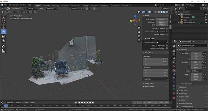
The model in blender – highlighted on the left, the “rotate” tool, and on the right, the “View Panel” is visible.
Click on the model. On the left side of the scene, select the “rotate” icon, and then use the different orientation rings until you’re happy that the floor is in the right orientation. Scale the model down at this stage too – we can tweak the final size in our next stage, but it’s helpful to make it perhaps 10% of the size now.
You may also notice that your model is missing it’s texture. In the top right of the viewport window, there are some viewport shading icons. Choose the “Material preview” and you should see the colors for your model show up.
You can also spend some time using Blender’s editing tools to make your mesh look prettier – fill in holes, delete extraneous faces. There are many tutorials out there that can help you do that, so we are not going to go into it here. Once you’re happy with the mesh, Export it as a “GLTF 2.0”. The file extension you actually need is the binary version of gltf, .glb.
Step 4: Importing into Mozilla Hubs
Mozilla hubs is a free platform that will allow you to bring other people into your space. We’re going to create a brand new room, import our model, and then you will be able to share it with other people.
Open Firefox, and go to hubs.mozilla.com. You’ll need to sign up for an account. Click on “Create a room” and then “Choose Scene”. Pick “Create a scene with Spoke”
Create a new project, and choose “New Empty Project”.
You should see an avatar representing your spawn point, and a crater terrain. In the bottom left panel, click on “My assets”. Upload your .glb file here, and then drag it into the scene by dropping into the hierarchy panel just above the crater terrain. Use the spawn point icon and the crater terrain as a guide, to scale your scene appropriately – we scaled our mesh to 0.002 from the size it came in at. You can keep or hide the crater terrain, add any additional objects like lighting.
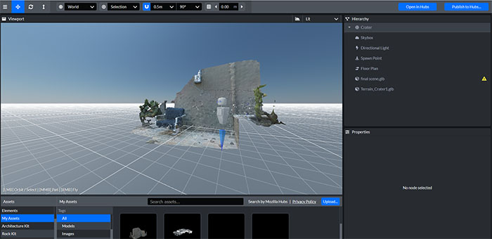
Spoke window showing our final scene in the hierarchy and the viewport, scaled to fit the spawn point model.
When you’re happy, select “Publish to hubs”. It’s likely that you have too many polygons – our mesh is quite detailed, so it may not perform well on mobile. Ideally in the blender stage, we would decimate our mesh to below 50,000 polygons to make it perform well. All the other performance parameters should be fine. Publish your scene, select “view your scene” and then “Create a room with this scene.”
Once you enter the room, you can share the link with others and show them your scan. This workflow should work for any point cloud object you scan using Dot3D pro or other Intel RealSense enabled software. Congratulations! You made a space that people can enter via a browser to chat with you, or even using a VR headset.
Here’s the final scene. Obviously, this could use some work to further optimize and improve the mesh we created from our original high quality scan, but with some time and effort, you can use this workflow to create something great.
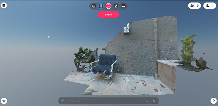
The final 3D scanned environment within the shareable, social Mozilla Hubs portal.
Subscribe here to get blog and news updates.
You may also be interested in
“Intel RealSense acts as the eyes of the system, feeding real-world data to the AI brain that powers the MR
In a three-dimensional world, we still spend much of our time creating and consuming two-dimensional content. Most of the screens